Last updated 11th June 2017
This is a low cost open source audio DSP filter for Radio Hams. It is released as a building block for anyone who wants to design or customise their own audio filters. It is different from commercial offerings because is can:
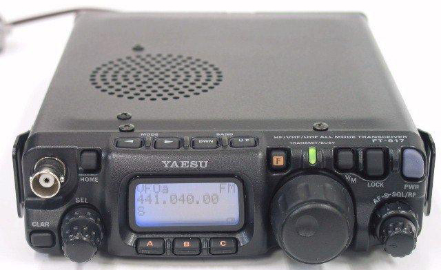
While I am using the board with a Yaesu FT-817 it is be easily adaptable to any other rig (Icom 706/Kenwood TS50 etc.) or fitted inside an amplified speaker as described later.
The design is based around a $19 Teensy 3.2 board plus a handful of components which most radio hams probably have in their junk box. The board is programmed using the Arduino IDE and takes audio in via an ADC, filters it using a software defined FIR filter and outputs it via a DAC.
The latest release:
I will add support for dual pass band filters next but this will require two rotary encoders making it suitable only for external speaker applications. Once I have done that I will probably add a small OLED display to allow the board to simplify using twin passband filters.
Note you cannot do audio processing on a normal Arduino. It requires a Teensy 3.2/3.5 or 3.6.
This project is only a starting point and not meant to be a detailed introduction to Teensy or DSP filters.
There are many other cool things that could be done with this board and audio library i.e. decoding and potentially encoding some types of digital modes, using a Teensy 3.5 and its second audio DAC to perform outgoing speech filtering....
Not sure how well it would work but I would also be interested in trying to use the filters in conjunction with tone detection to regenerate a Morse tone with no direct audio pass-through i.e. no static just a pure regenerated tone produced by the board in response to received Morse.
Any comments or suggestions should be made via https://forum.pjrc.com/threads/44372-Open-Source-DSP-Audio-Processor-for-FT-817
Just want to try it without the hassle of setting up a development environment?
Download a recent HEX file from the "bin" folder and use the Teensy command line loader as described here
This is well documented on the Teensy Web Site in principle you need to:
Once you are happy with the basics you can try out the DSP Sketch with its sample filters and then move on to creating your own filters and voice prompts!
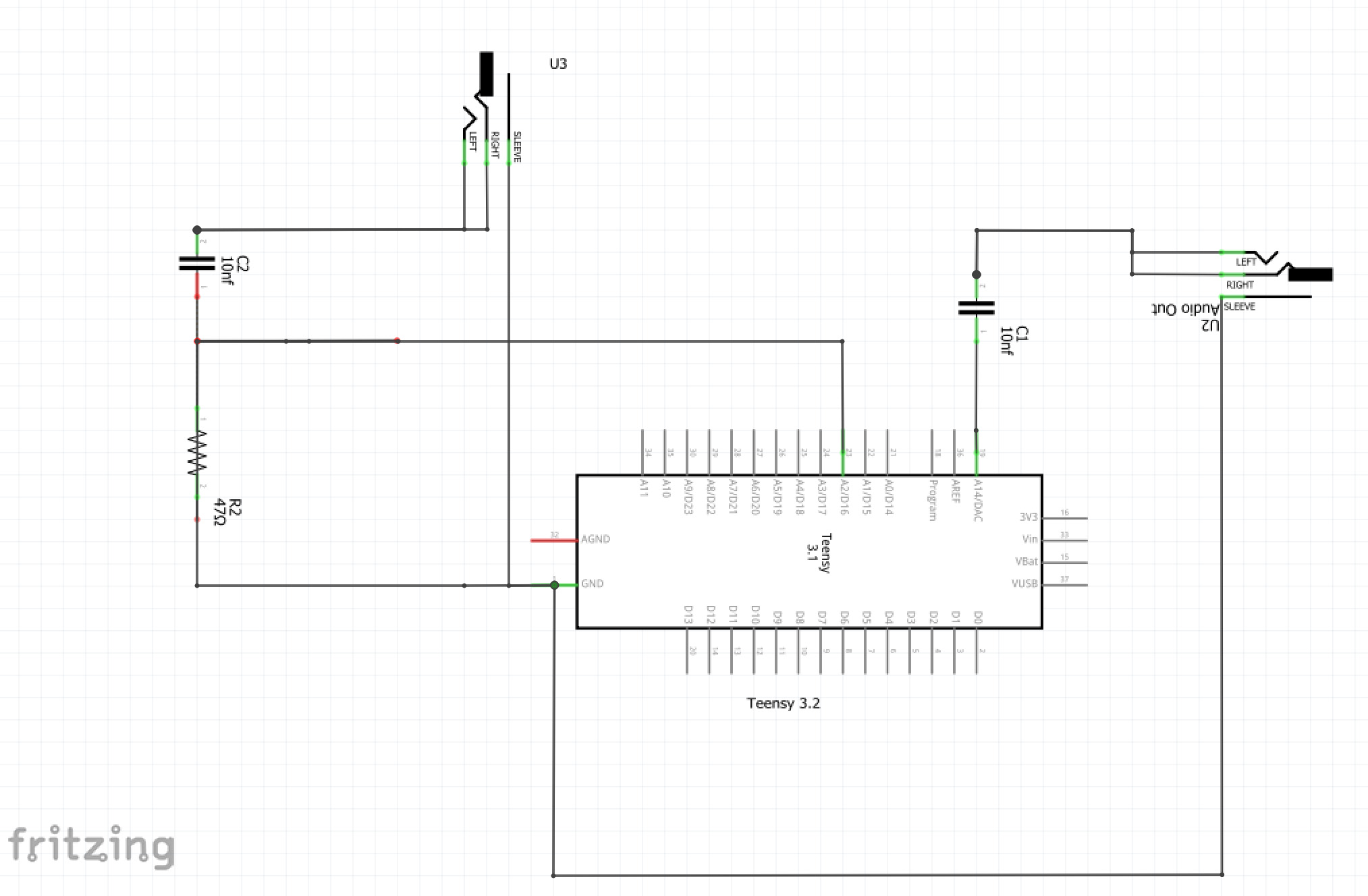
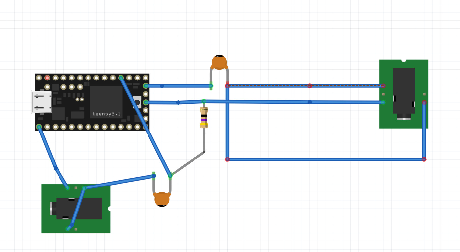
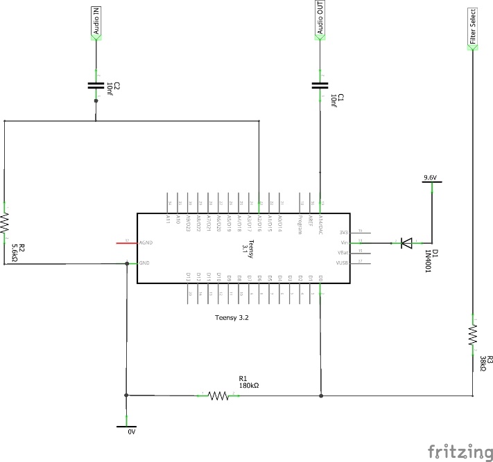
You can test the board using any rig by simply feeding the sets audio output into the audio input of the Teensy. A 50ohm resistor acts as a load while a 10uf cap decouples the audio input. The Teensy DAC is then to an amplified speaker via a 10nf cap.
You will need to check the debug output using a terminal to make sure the peak values generally don't exceed 1.0
You will also probably want to modify the code to change the pinMode from INPUT to INPUT_PULLUP so you can simply use a switch between GND and PIN0.
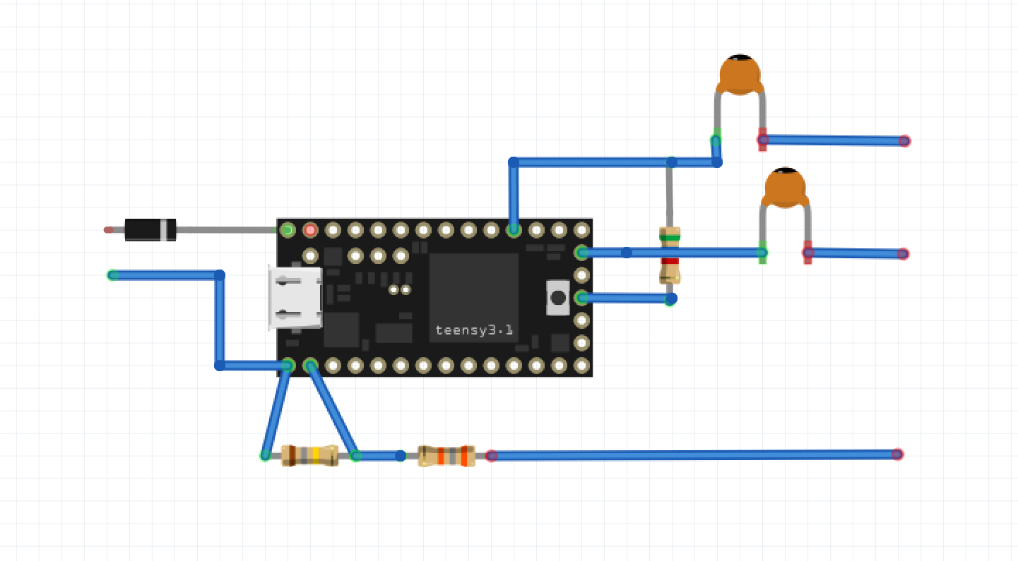
I'm hopeless at using Fritzing but these images should give you a rough idea of how to wire it up
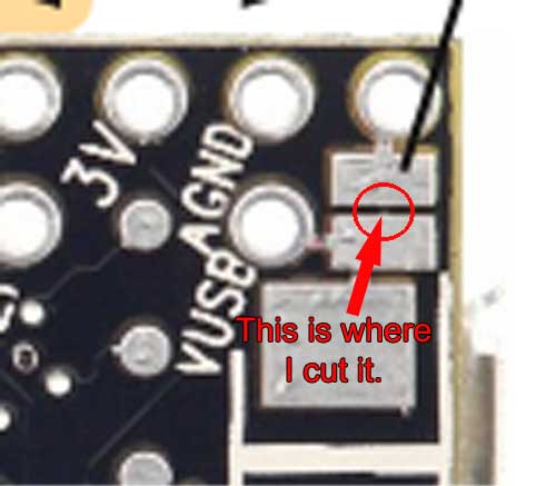
WARNING:
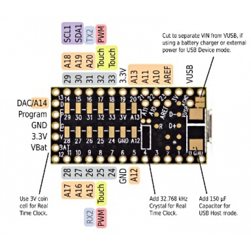
Make sure you cut the PCB track on the Teensy which connects the external RAW and USB power together. Failure to do this may damage your PC USB port if the board is fitted to the FT-817. Cutting this track means the Teensy is no longer powered via USB.
Fitting the Teensy DSP filter to an FT-817 requires the following:
Remove the top cover from the FT-817
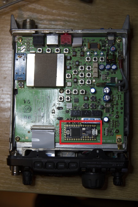
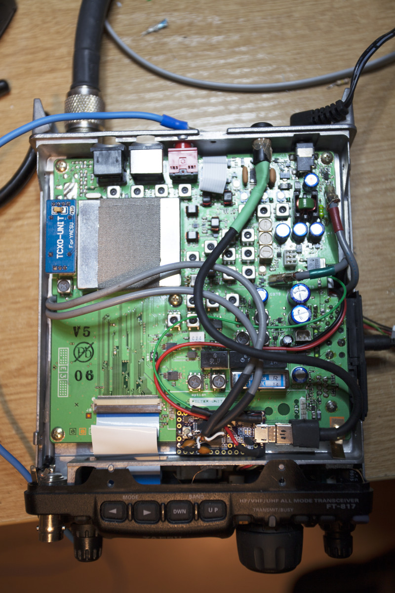
Planned fitting location for the Teensy
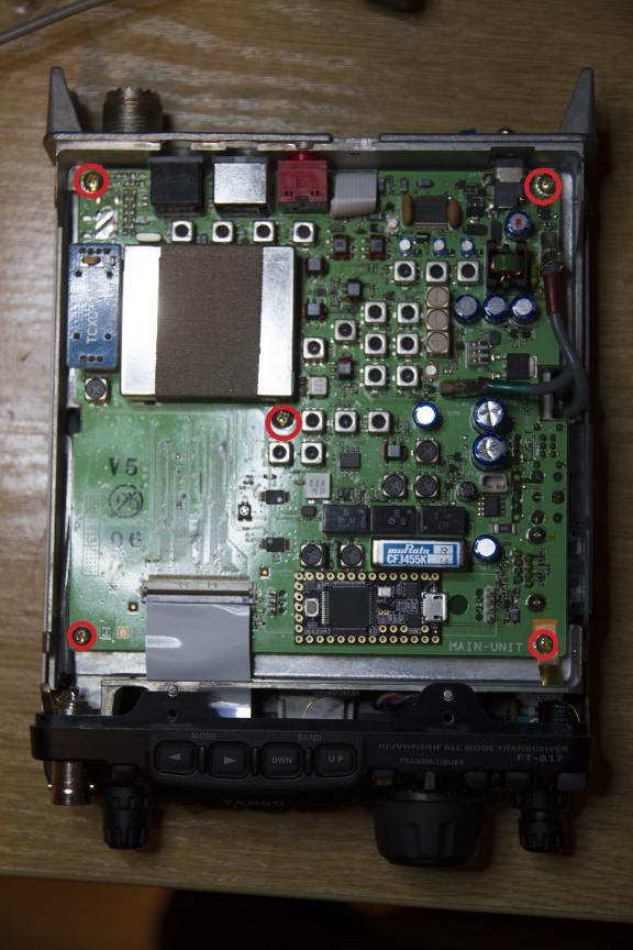
Remove the five screws holding the main PCB |
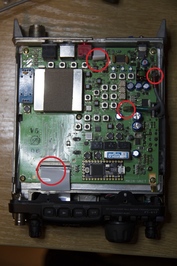
Unclip the cables |
PWR is taken straight directly of the FT817 PCB. On my rig this provides 9.6V when the FT-817 is used with a 13.8V external power source. The voltage regulators fitted to the Teensy 3.2 boards are a LP38691 which is rated at 10V max (Teensy documentation states 6V max). I added an inline power diode to drop the input another 0.6V to create some headroom. While close to the limit the regulator does not get excessively warm.
Alternatively, you can tap a 5V supply of the TCXO module on the top of the PCB and ditch the diode. I have an aftermarket temperature controlled TXCO fitted which is the blue module marked TXCO-UNIT towards the back of the rig on the left-hand side in the images above. If you look closely you can see a yellow titanium cap which is across the 5V rails. If I ever make this mod i'll document it properly.
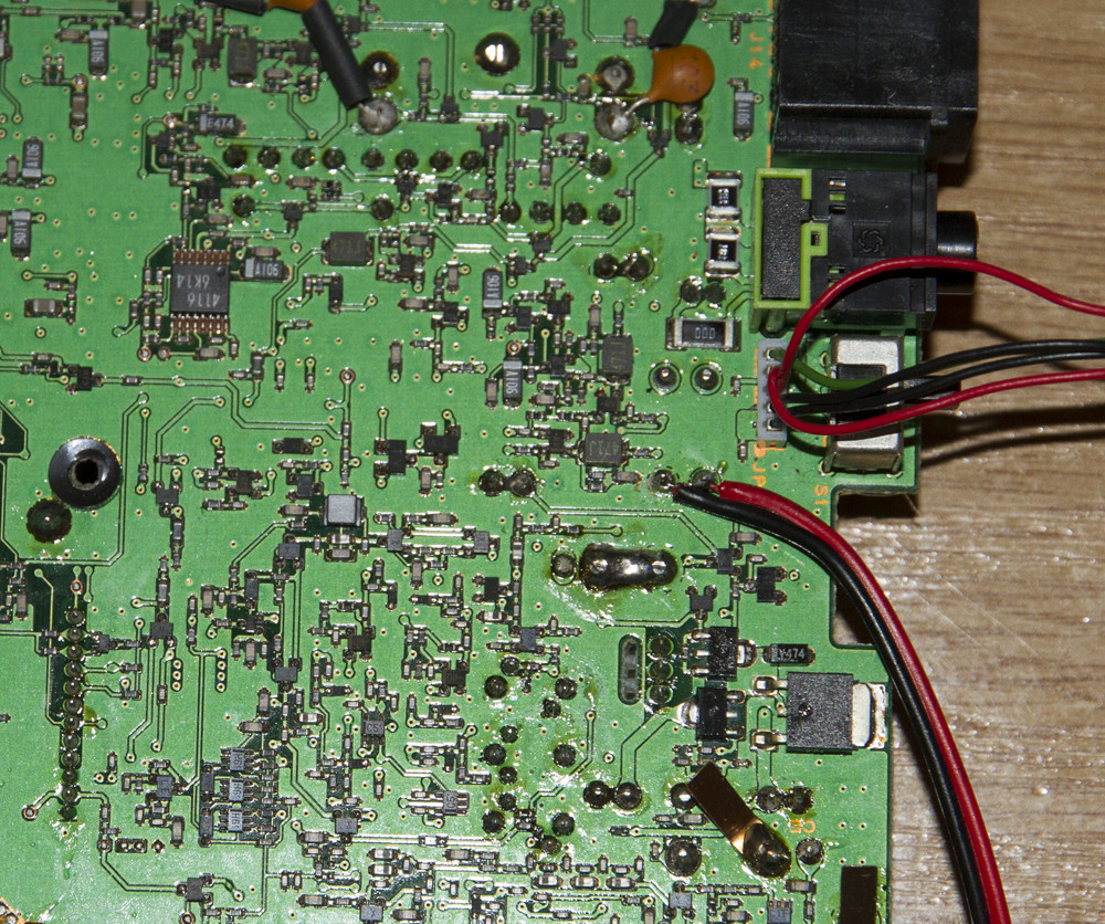
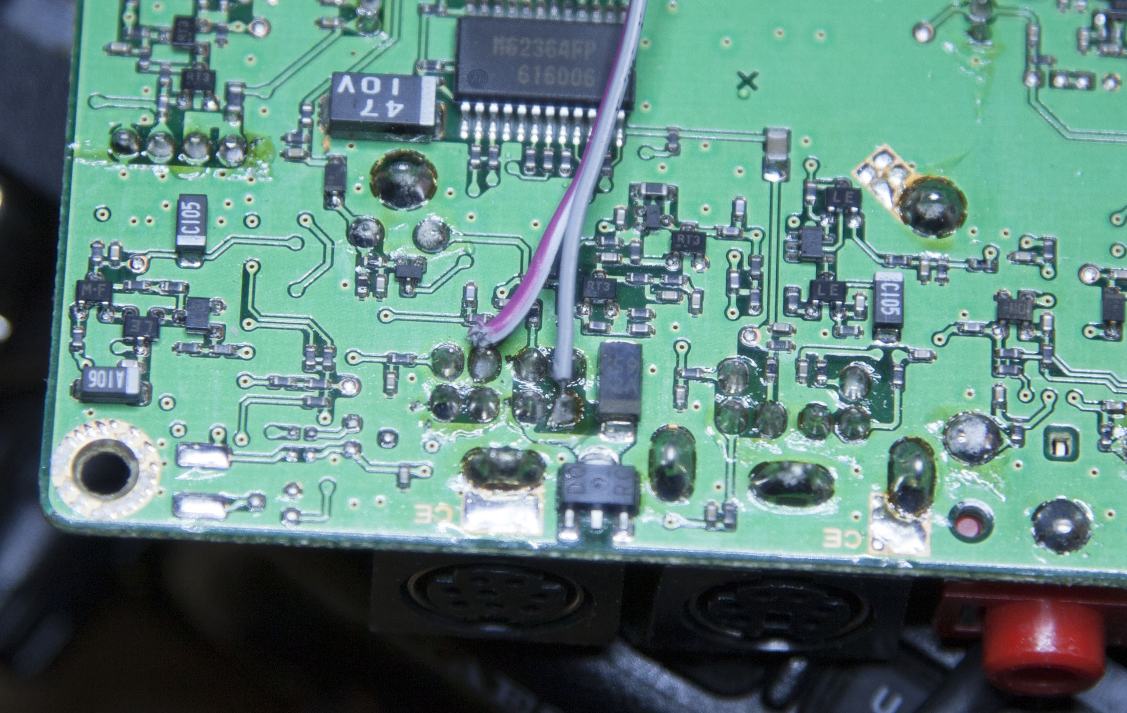
Remove C1338 and attach two shielded audio cables as below. You can easily determine which is the audio amplifier by simply tapping the bare end and listening for mains hum.
Audio input to the Teensy is accomplished using one of the ADC convertors on pin PA2. This is decoupled from the FT817 via a 10nf ceramic cap. I used a 6.8K resistor between PA2 and GND to limit the input as it was saturating the ADC. You can verify if you need to adjust this value later using a terminal emulator connected to the Teensy once the code is loaded.
Audio output from the Teensy comes from the internal 12bit DAC. This has a much higher quality output than PWM outputs used by most single chip systems. Again, the DAC is decoupled from the FT817 via a 10nf ceramic cap.
Use the built-in debugging info to ensure the audio level remains mostly bellow 1.0. If it constantly exceeds this level, you will need to lower it by changing the input resistor or change it to a proper voltage divider.
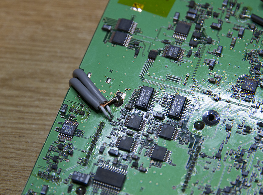
You can skip this if you have a physical CW filter fitted. Otherwise add two 10nf ceramic caps as shown below. These act as an audio pass-through for the missing filter when it is selected.
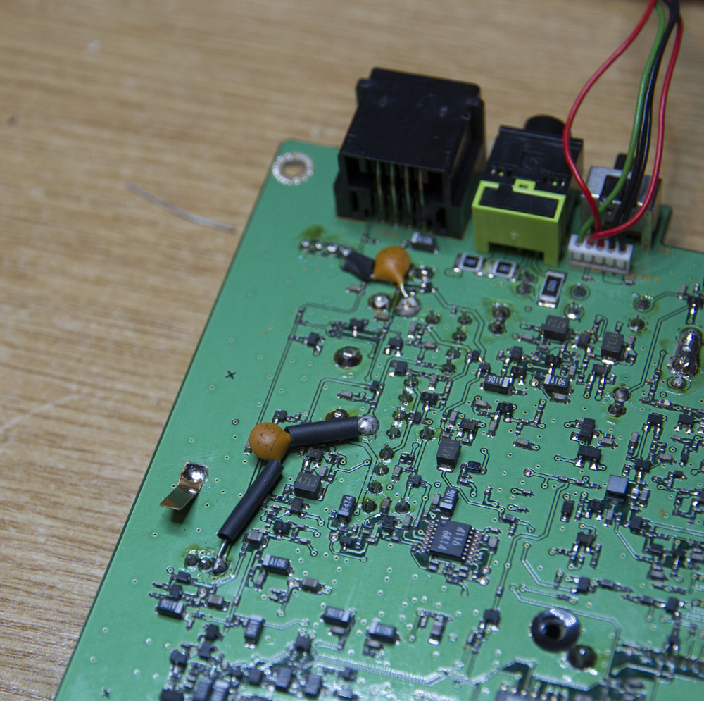
For the moment add a small signal wire (green wire) as shown below. This is used to switch filter modes.
Connect the wire to PIN0 on the Teensy which is configured as an active low input toggle. It is used to select between the different audio filters. Since the signal I am using from the FT817 has a level higher than 3.2V it is feed via a simple voltage divider consisting of two resistors. The Teensy has 5V tolerant inputs.
In the future, I aim to take mode signal(s) from switching IC Q1049 allowing automatic selection of filters based on the modulation mode of the radio.
With the cables fitted it’s time to resemble the radio ensuring no wires are trapped or nipped.
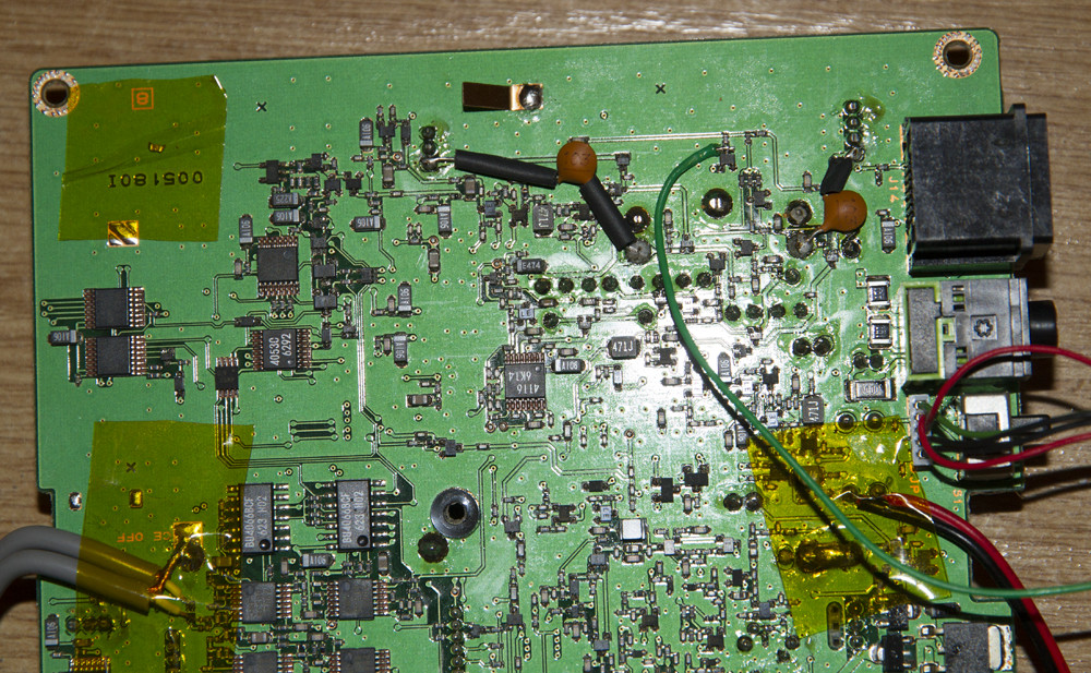
If you uncomment "#define CAT" in the setting.h file and disable all debug messages you can also use the Teensy as a UST->CAT interface. This requires serial port 2 on the Teensy to be connected to the FT817 CAT interface. Serial port two on the Teensy using pin9 for RX and pin10 for TX.
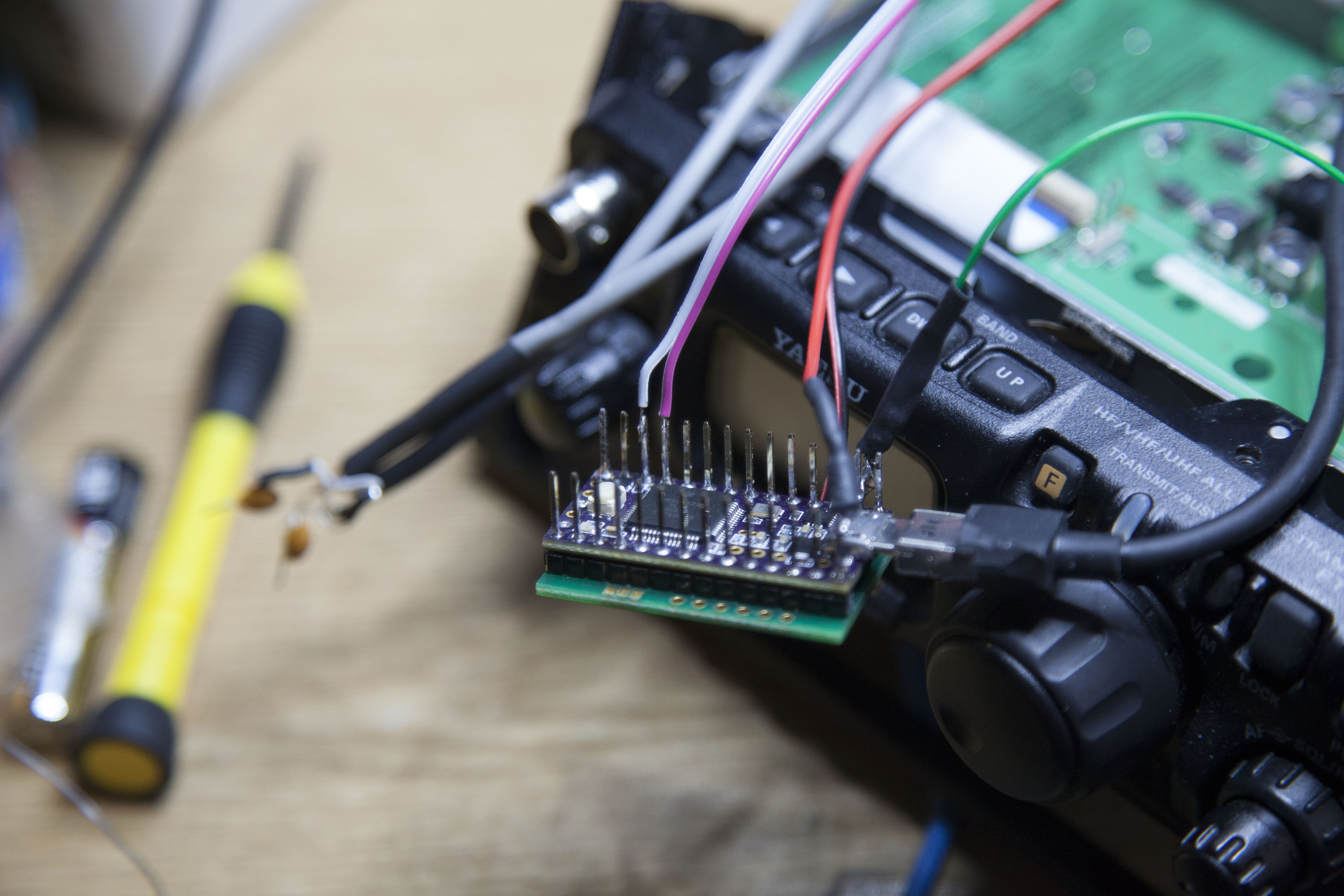
The following image shows two wires tapping off the CAT RX and TX lines.
The following image shows the two lines connected to serial port two on the Teensy. In this case I have the Teensy WIZ820IO board attached to provide a SD card slot. This is optional and only required for some speech features.
If you have the CAT connection made and a SD card slot attached, you can enable a speech readout of the FT817 configuration. To do this simple uncomment "#define SPEECHCONFIG" in the settings.h file. This feature could be handy for the visually impaired.
I have not tested this with CAT rig control so for now either use the CAT interface for speech readout or PC control but don't do both!
Morse decoding is performed using an implementation of WB7FHC's Simple Morse Code Decoder. I admit I had thought I would be able simple to do this with the Teensy 3.2 board but I ran into two problems that limit the current implementation to a Teensy plus audio board.
The first issue was simply not enough space to hold the voice files consisting of the alphabet plus numbers and a few special characters. Even at 10K per file or less I simply could not get that much audio stored into the available flash memory. So I then tried LPC coding which most people know as Speak'n'Spell voice synthesis. That works and is still in the code but it seriously limits the fastest decode rate which can be supported. This is simply because LPC requires a lot of CPU cycles causing the decoder to miss the Morse transmission.
Both these problems can be solved by using speech stored as WAV files on an SD card. The SD card eliminates any storage issues and WAV playback is off loaded to DMA hardware on the chip so the processor does not have to do much freeing it up to continue decoding. Even here I ran into a slight issue. I had to buffer characters as they are being played back since most Morse code is transmitted faster than it can generally be spoken. This is not a major issue as the spoken word catches up during the gaps in the Morse transmission. What I may try doing if speeding up the audio in the WAV files while maintaining the pitch to reduce the overall time delay.
Ultimately the Teensy SD board should allow this functionality to be added to the FT817 version.
All the important configuration options are in the settings.h file. It is self documenting.
Since I am not worried about power consumption I build and test the Teensy running at its fastest speed of 96Mhz.
If you want to recover as much power as possible for battery operation you can compile for a slower clock speed. At 48Mhz the Teensy 3.2 board draws about 30ma and should still be able to run the existing code without issue.
Going below this point requires the number of filter coefficients to be reduced to around 120 otherwise the CPU cannot complete everything it needs to do in time. At 120 coefficients, you do this you should be able to compile for 24Mhz which will reduce consumption down to around 22ma.
Also, don't forget to set the IDE "tools/optimise" setting to "fastest" to optimise the code for slow clock speeds.
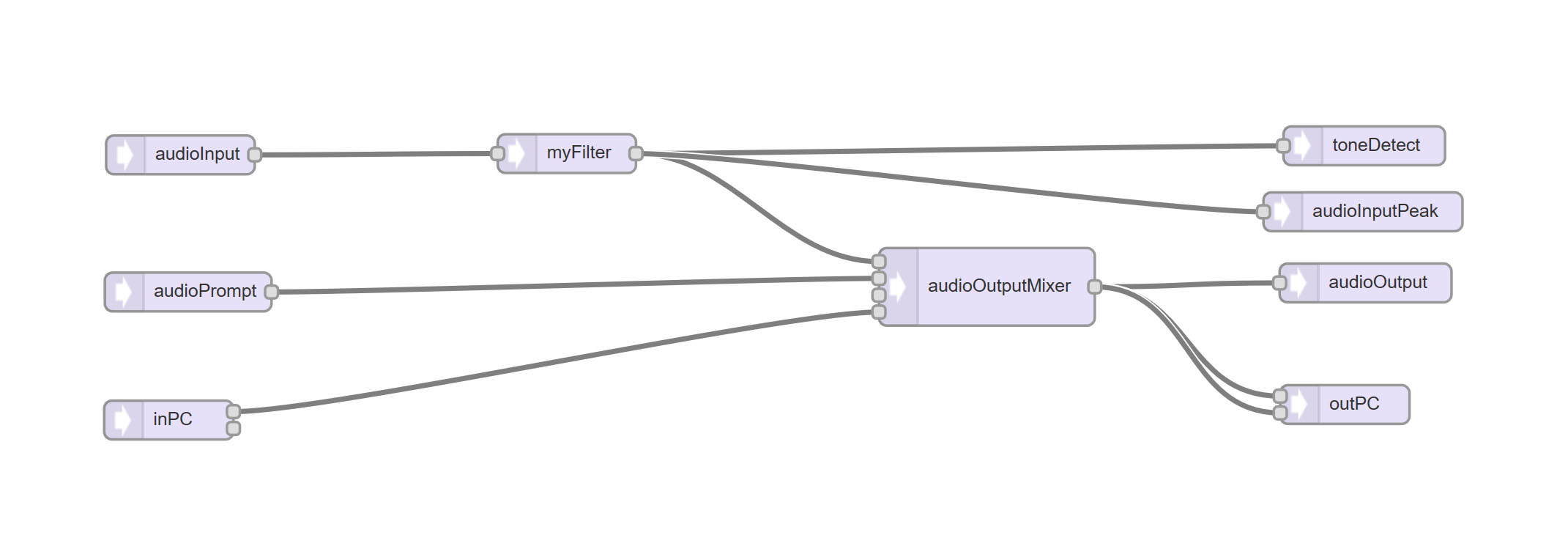
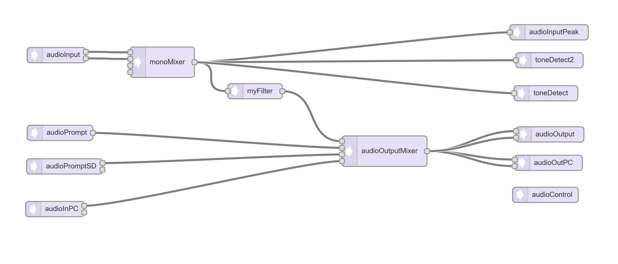
The following diagram provides a very simplified overview of the software components.
audioInput is via an ADC converter. It is patched into a a FIR filter (myFilter) that does most of the hard work. A toneDetector (toneDetect) provides the basic detection mechanism for the morse decoding. A peak level detector is used for debugging to make sure the audio is not being overloaded. The output from the FIR filter is mixed with audio coming from the PC (the Teensy is configured to look like a USB sound card - inPc) and audio playback from flash rom (audioPrompt). The output from the mixer is feed to the DAC (audioOuput) and back to the PC again via the emulated PC soundcard interface (outPC).
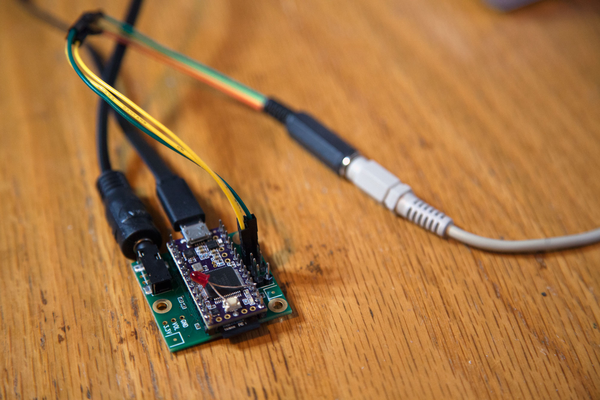
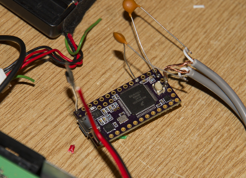
This is my Teensy and Teensy audio board test rig. The LED is connected between pin15 and GND and is used to signify a Morse tone detection. I know I'm not using a current limiting resistor but you should not follow my bad example.
The Teensy audio design tool looks like this. The primary differences are a down mixer from stereo to mono, SD card WAV playback and I2S audio inputs/outputs.
As you can see there are only six components external to the Teensy.
Once programmed the device will appear as a standard serial port. Use the built in Arduino IDE Serial Monitor or a terminal program of your choice to connect to the board at 115200 Baud, 8,N,1.
Debug output format
This was my initial hacked together audio used in testing before I discovered the level was too high.
The following images shows my test board and power connection and the shrink wrap ready to go. Initially I was using PIN1 as the mode switch as show in the photo. I have since switched to PIN0 as reflected in the sample code to simplify the hardware.
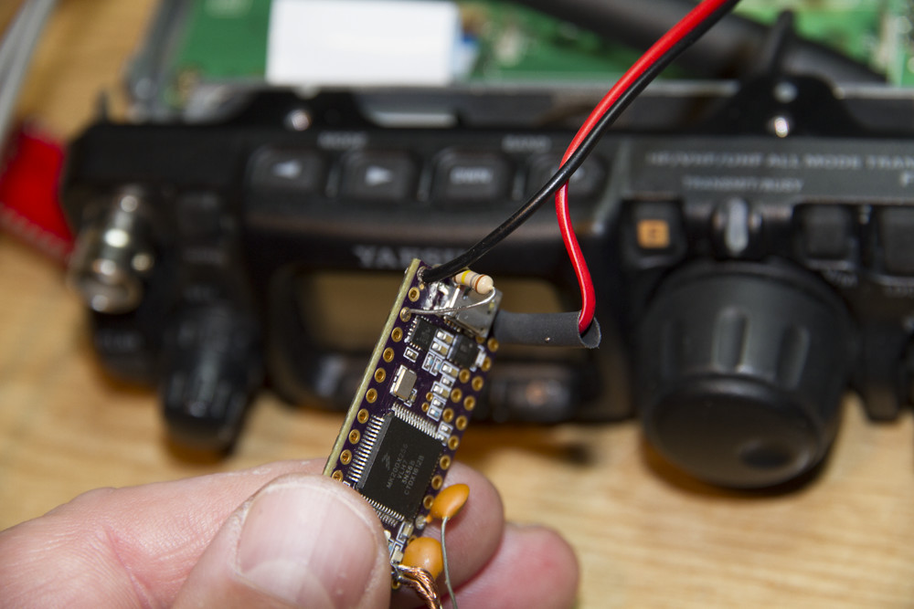
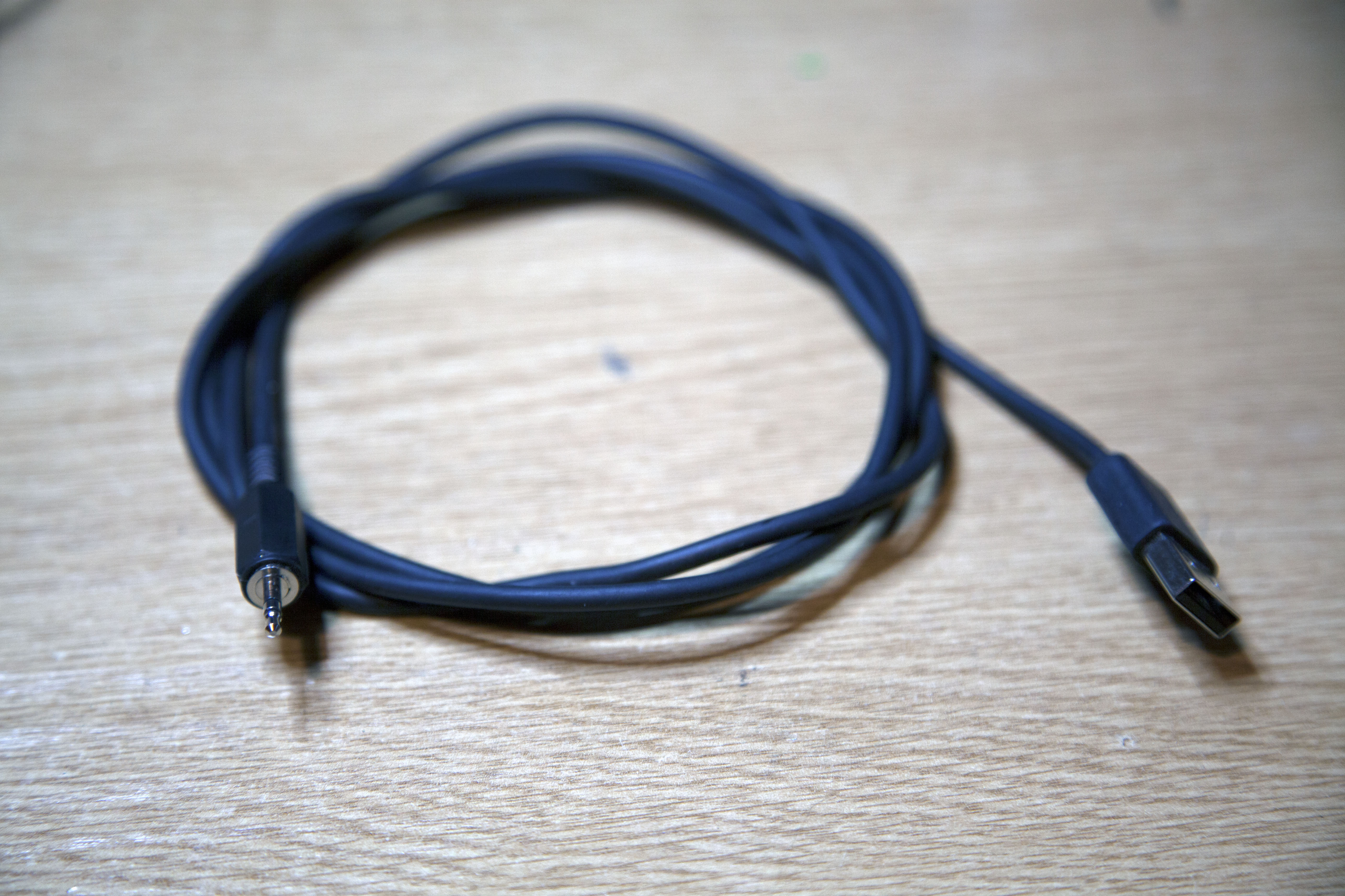
This is the board installed with the USB brought out the rear on a 2.5mm stereo jack. Only GND, DATA+ and DATA- are used since power is provided via the rig. The latest code release allows the Teensy to act as a USB sound card (RX only currently) and a CAT interface (this still needs testing).
If you are wondering why the USB plug was hacked to bits it was because I was trying to see if I could get it through the 2.5mm socket hole and no you can't!
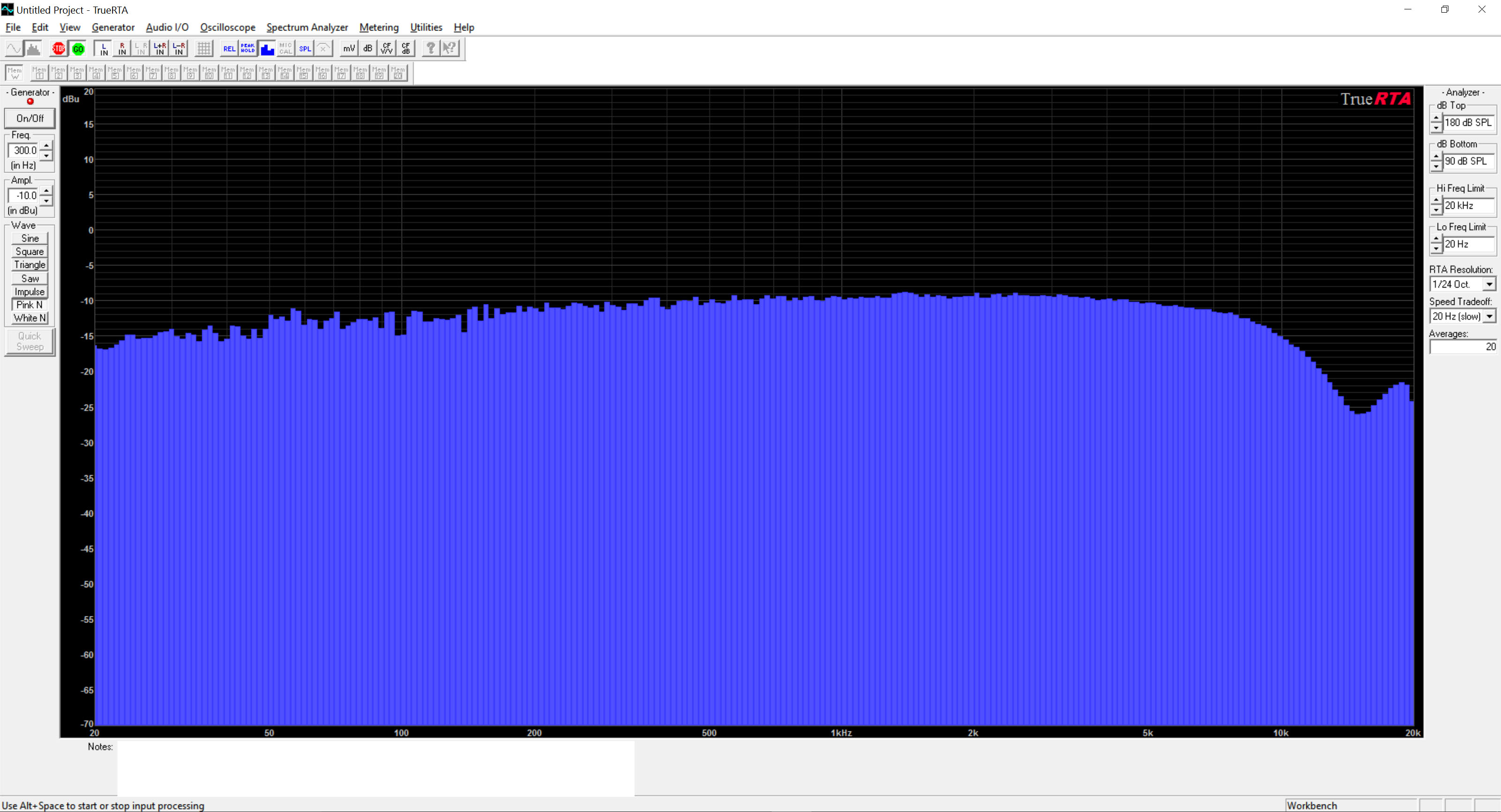
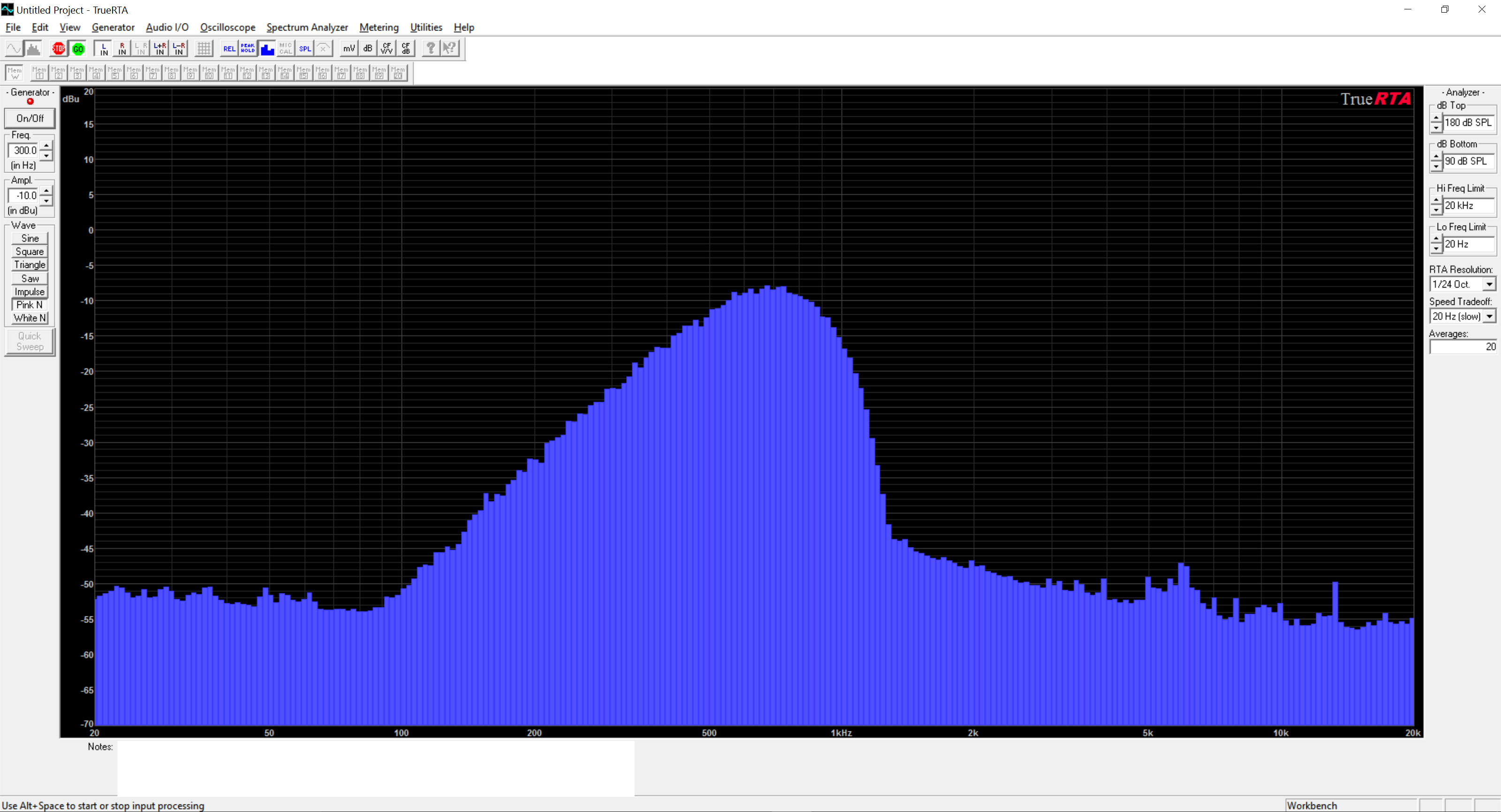
The following are real measurements using a pink noise source and a PC based audio spectrum analyser. I used the Teensy attached to a Teensy audio board to simplify the hardware setup for the testing. So, it identical to what you should get if using it in an external speaker. I doubt there would be any noticeable difference when fitted without the audio board inside a rig.
The filters are generated by the code from user specified frequency cut points using the default 200 coefficients (Maximum accuracy allowed by a non-modified library) and a W_HAMMING window.
When I get some time I may run the test again with different window functions and possibly increase the max coefficient size in the Teensy audio library (see filter_fir.h, #define FIR_MAX_COEFFS)
First let’s have a look at physically bypassing the Teensy for reference:
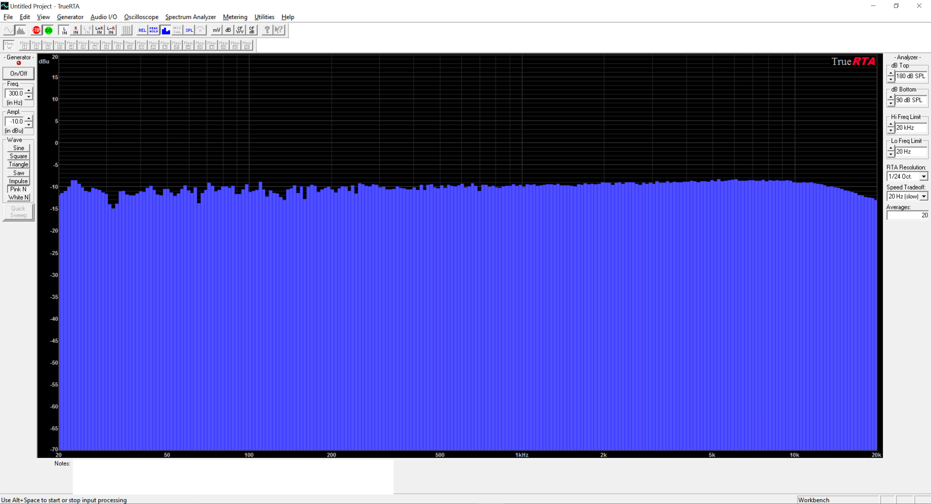
Now for the board in circuit but operating in pass-through mode:
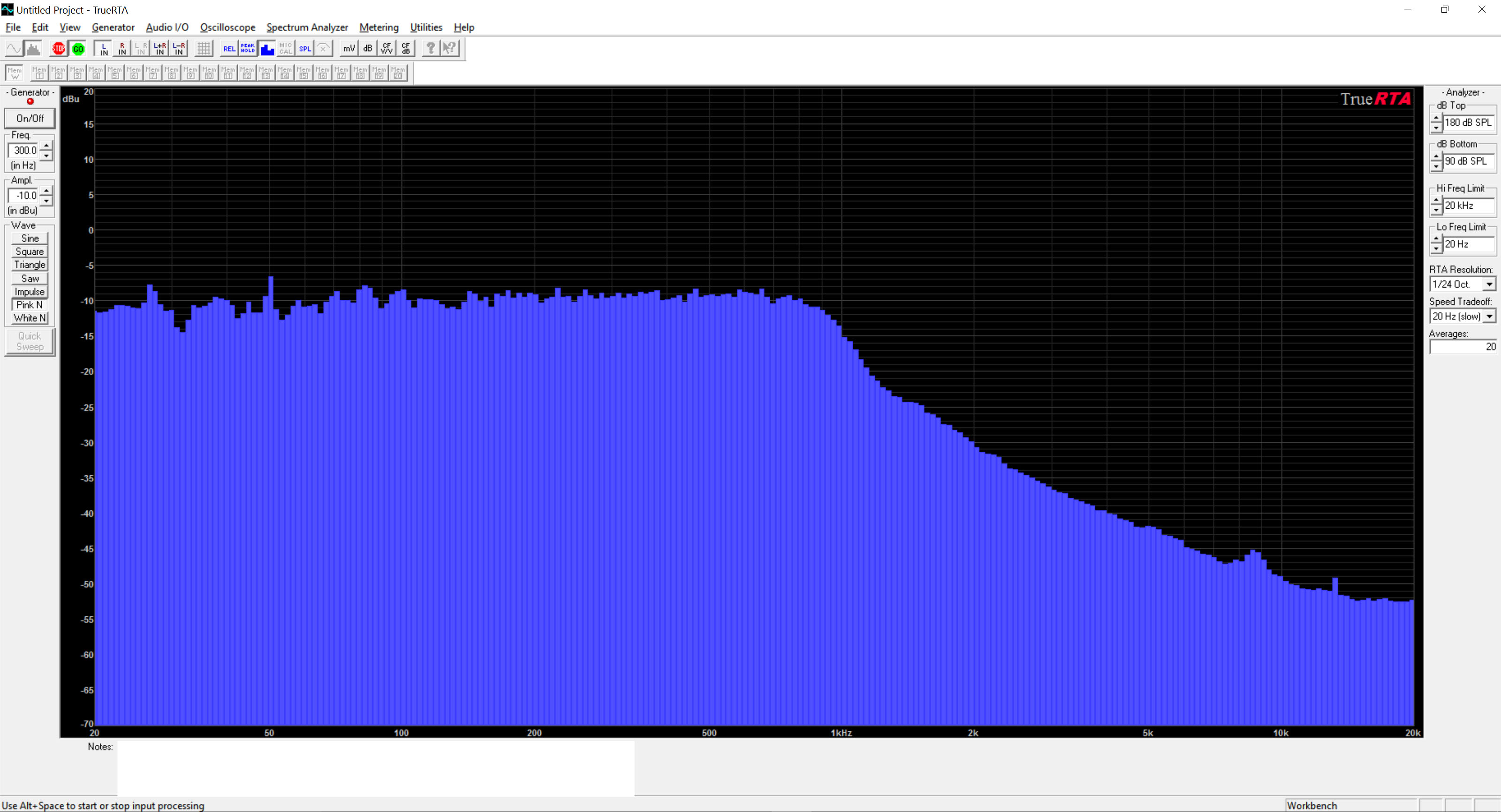
Now for a low pass filter set for 1Khz:
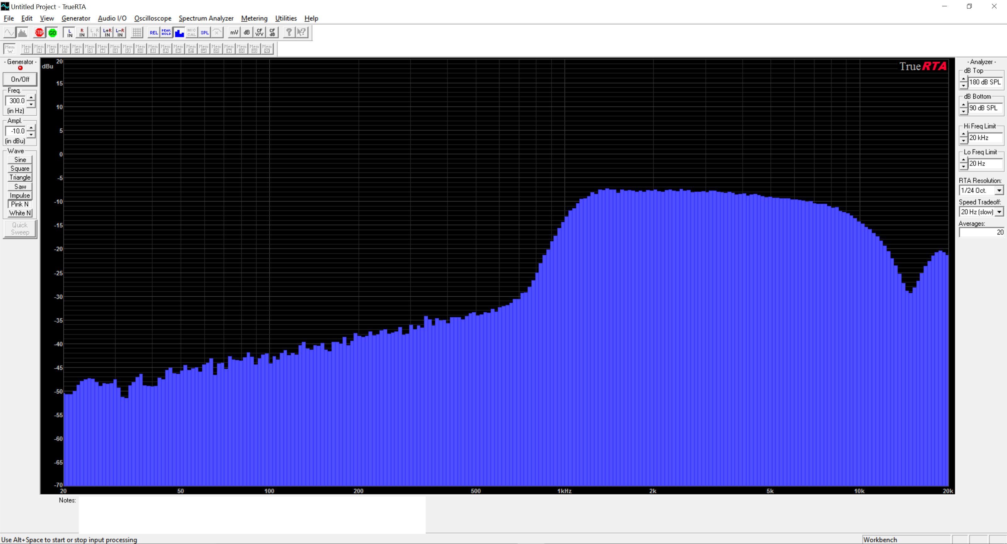
Next a hi pass filter set for 1Khz:
Next a pass-through filter for SSB i.e. 300Hz - 2.7Khz:
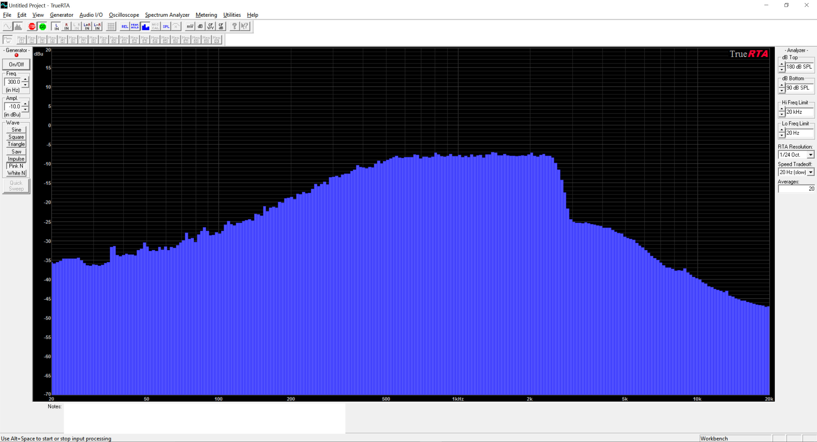
and lastly a band pass Morse filter i.e. 450Hz - 950Hz
This section is no longer required unless you have a special requirement. You can now simply specify the filter details in the "filterList[]" array and the coefficients will be generated at runtime. You can also uncomment "#define SHOWCOEFF" which will list the calculated coefficients in .COE format allowing import into MATLAB for analysis.
However, if you want to create your own filters try the following.
Go to http://t-filter.engineerjs.com/ and use the Predefined drop down to select one of the predefined filter types such as Bandpass.
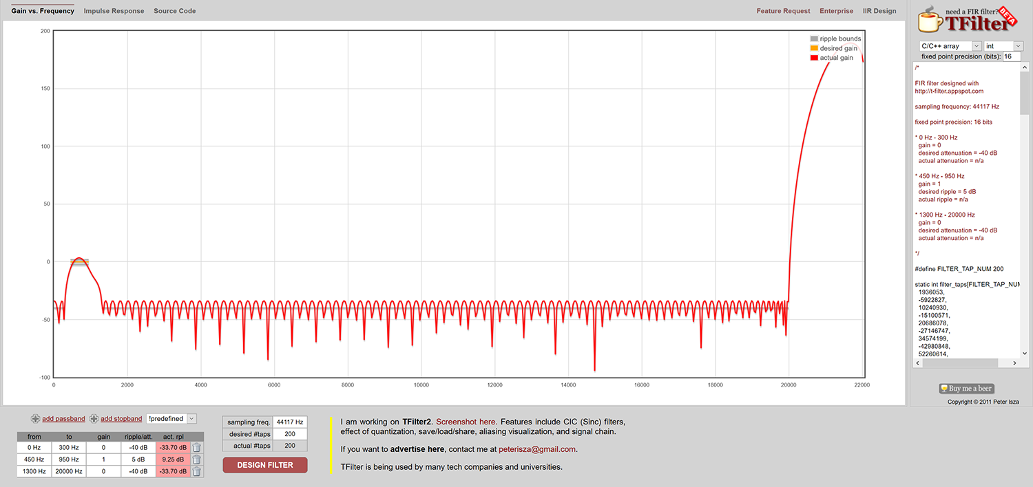
Change the frequency to 44117 HZ.
Now modify the filter to obtain the desired result.
Use the “Filter Design and Analysis” button to recalculate the design as required. Note it is important to set the maximum number of taps or check the actual number of taps has an even number and does not exceed the Teensy maximum of 200. If this is a real problem, modify the code to daisy chain multiple filters together. You should be able to chain three or four filters before maxing out the processor (check debugging for CPU utilisation info).
When you are happy you can export the coefficients as a 16bit int "C/C++ array" option. You will need to modify the "int" to "short" in the generated code for it to work with the Teensy.
Now you can update filters.h to add your newly designed code and then add the new filters into the “fir_filter fir_list” array in the main Sketch using the existing code as an example.
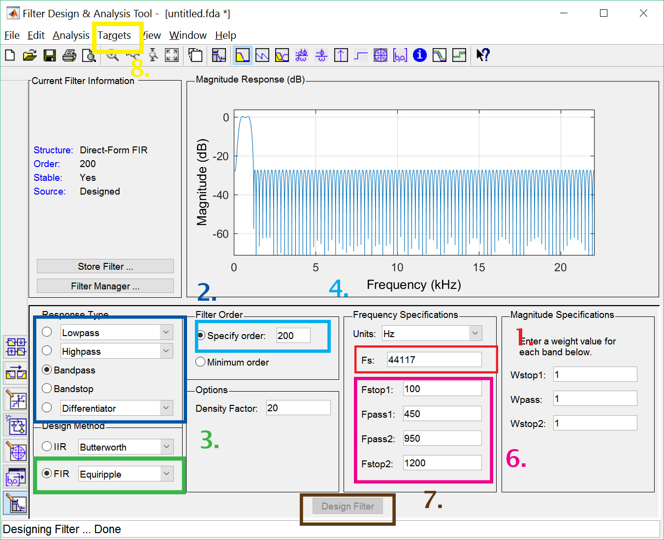
Fire up MATLAB and go to the APPS menu. Then select the “Filter Builder” app under “Signal Processing and Communications”.
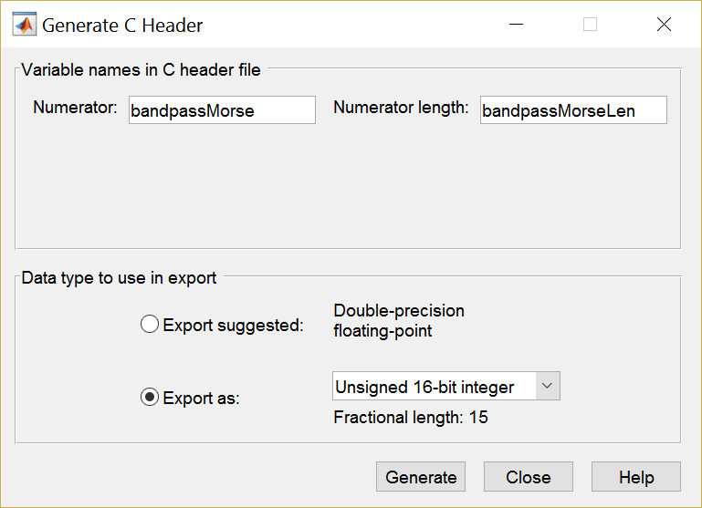
The Numerator and Numerator length are simply the names used in the generated file for the coefficients. I would recommend using something line filterXXXXX and filterLenXXXXX if creating new filters
Export the files as Unsigned 16bit integers for compatibility with the Teensy development environment. The files should be saved into your development environment.
You can then update filters.h to add your newly designed code and then add the filters into the “fir_filter fir_list” array in the main Sketch using the existing code as an example.
You will need to comment out or delete the line #include tmwtypes.h in the generated .h file. you will also need to modify the variable types from:
const int bandpassMorseLen = 200;
const uint16_T bandpassMorse[200] = {
To:
int bandpassMorseLen = 200;
short bandpassMorse[200] = {
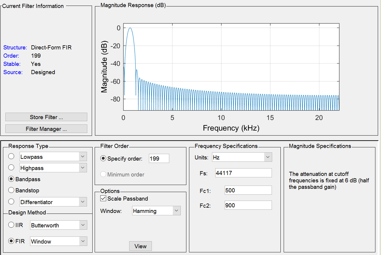
The above image is the simulation of the actual Morse filter used in the code. It may be too sharp for some people. But that should be OK as you can create your own!
To simplify creating audio files for this project and to make them more consistent I switched to using text to speech synthesis. This should make it a bit easier to change voices i.e. Male/Female and to even change languages.
If you look in the "SD files" folder you will find a BAT file called makeWavFiles.bat. This will generate the necessary WAV files required by this project. These WAV files need to go on a SD card attached to the Teensy.
Since some of the speech functions happen even if a SD card is not fitted some of the WAV files are embedded into the code. To do this there is another directory called "Code Audio Files". Another script inside that folder takes some of the generated WAV files and convert them into CPP and H files for use by the compiler. This should be run if you update the voice prompts.
Audio prompts are used to identify filters as they are selected. Creating a new audio prompt requires creating a suitable WAV file and then converting that into a data (C Array) for use inside the application.
An easy way to create the WAV file is to use the online system https://online-voice-recorder.com/ this allows you to record a message and trim it to suit. When you are happy you can save the final message to a directory on your computer.
Now use http://audio.online-convert.com/convert-to-wav to convert the saved MP3 file to the WAV format. You can drop the audio quality down (try 8bit@11025hz) to save flash memory in the final code. After all it's not like we need HD audio for this application
Tip: if you need to perform batch conversions have a look at audacity and lamexp
WAV file conversion requires a windows command line application called wav2sketch. Simply put it in a folder along with the WAV file(s) you generated earlier and run it. Detailed instructions can be found here.
Once the conversion has finished it will have created a CPP and H file for each input WAV file. All you need to do is add these to you project using the existing sample files as examples.
A while ago I spotted some third-party add-on DSP filters for the FT-817. A quick visual inspection of the product photographs showed they were probably based on the PIC32MX range of microprocessor and like any good hacker I ordered up a couple of low cost dev boards.
While waiting for the boards I started researching DSP filter implementations including reading the DSP chapter in the ARRL handbook. This was all well and good but I did not turn up any great examples of working code.
Anyway, by the time the boards arrived I had become started some other projects so the boards were consigned to my growing stash of low cost processor boards with the aim of looking at them at some point in the future.
Jump forward a month or so and I happen to be reading an article on Hackaday covering the use of a Teensy board as an audio synthesiser. After watching the linked video of the device in action I became intrigued as to how such a low-cost device could generate incredible audio.
At this point I had never looked at the Teensy in detail. I knew it used the Arduino IDE and that many of the Arduino libraries would work on it but I thought it was just a faster Arduino clone. What a mistake that was.
Turns out the Teensy is based on a Freescale ARM Cortex M4 processor which includes a wide range peripherals including two analogue to digital convertors, a 12bit digital to analogue convertor, 64K RAM and 256K Flash. It also supports a range of DSP instructions.
What made it even more interesting was the PJRC the developers of the Teensy had released an audio library for the board making digital audio very straight forward.
As luck, would have it I happened to have a few Teensy 3.2 boards on hand (impulse purchases from using OSH Park PCB services). So, a few minutes later I had a development system configured and had run through a few of the Teensy audio examples. Within a couple of hours, I had my first working DSP filter – very cool!